Leave Your Message

What Are Exterior Cladding Panels and How Are They Used?

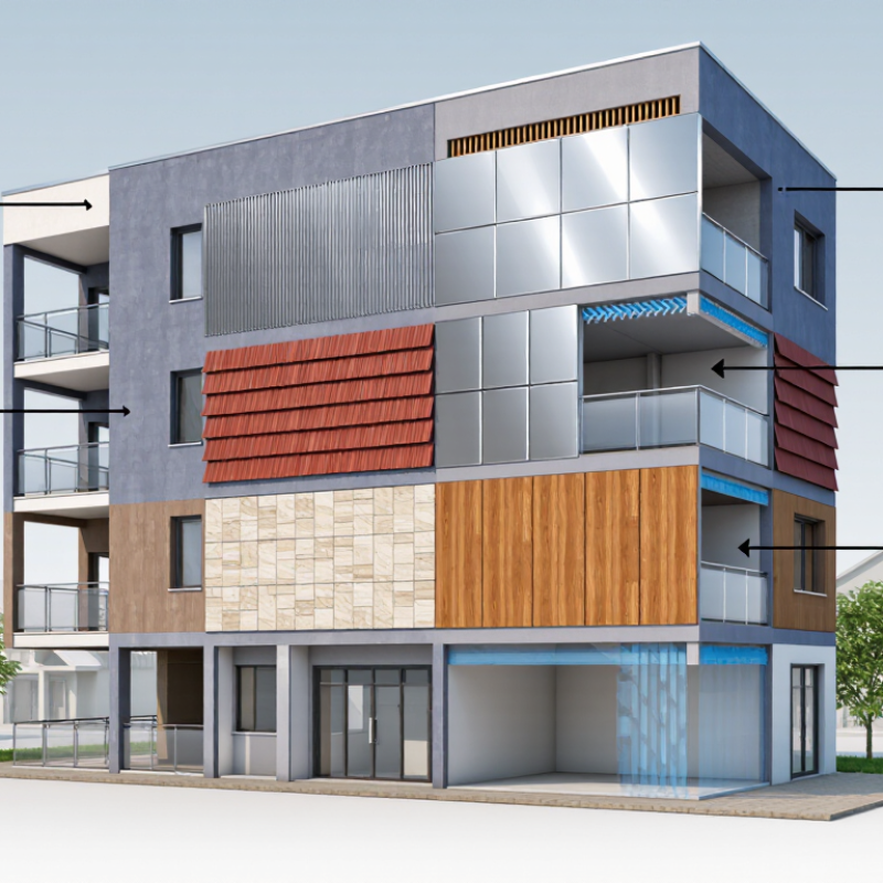
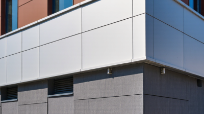
Exterior Cladding Panels shape a building’s appearance, but their purpose extends beyond visual appeal. They form an outer layer that can help manage rain, wind, sunlight, and temperature changes. Common options include fiber cement, metal, aluminum composite, high-pressure laminate, terracotta, and engineered stone panels. Each material behaves differently. Some resist impact well. Others offer lighter weight or simpler installation.

Building scientist Joseph Lstiburek often reminds professionals, “A wall is a system, not a product.” That principle matters when selecting Exterior Cladding Panels. A panel cannot compensate for poor drainage, weak framing, incorrect fasteners, or badly sealed joints. Behind a finished facade, a narrow ventilated cavity may help moisture escape. Flashing should direct water outward. Movement joints should allow materials to expand and contract without cracking.

These panels appear on homes, offices, schools, retail buildings, and renovation projects. They may cover an entire facade or highlight entrances, balconies, and upper stories. The final result depends on more than the panel itself. Substrate condition, local climate, fire performance, thermal goals, and maintenance access all influence the specification.

The process is not always perfect. A visually attractive system may still create hidden moisture risks. A low-cost option may demand more frequent cleaning or repairs. This guide examines what Exterior Cladding Panels are, how they are used, and where their practical limits deserve careful attention. Expect useful details, but also a necessary question: does the chosen cladding truly serve the building over time?

What Are Exterior Cladding Panels and How Are They Used?

Definition and Role: Cladding Panels as the Building’s Weather Skin

Exterior cladding panels form the building’s weather skin. They cover exterior walls and help control rain, wind, sunlight, and temperature changes.

Unlike structural walls, panels usually do not carry the building’s main loads. Their value comes from layered protection. A panel sheds water, while joints, membranes, flashings, and drainage spaces manage moisture behind it. Small details matter.

Common materials include fiber cement, metal, stone veneer, high-pressure laminate, and engineered composites. Each material responds differently to heat, impact, salt air, and fire requirements.

Panels may be fixed to masonry, concrete, or a framed support system. Installers align them over a ventilated cavity when the wall design requires drying space. That gap can reduce trapped moisture and improve long-term durability.

Good cladding work depends on more than attractive surfaces. A site team should check panel movement, fastener spacing, corner details, and sealant joints. Water testing can reveal weaknesses around windows and penetrations.

In practice, even a strong panel can fail when the flashing is poorly fitted. Maintenance also deserves attention. Dust, staining, loose fixings, and damaged edges should be recorded during inspections.

Some design assumptions prove too optimistic. A shaded wall may age slowly, while a sun-facing elevation can fade, expand, or crack sooner than expected.

Panel Families: Metal, Fiber Cement, HPL, ACM, and Terracotta Systems

Exterior cladding panels form the building’s weather-facing skin. They manage rain, sunlight, wind, and ventilation. The UNEP Global Status Report for Buildings and Construction 2023 states that buildings used about 32% of global energy in 2022. Therefore, panel selection affects more than appearance. It influences insulation, maintenance, fire performance, and embodied carbon.

Metal panels suit clean lines and long elevations. Steel offers high strength, while aluminum reduces weight. The International Aluminium Institute reports that recycled aluminum requires about 95% less energy than primary production. Fiber cement panels provide a mineral appearance and resist moisture, but installers must protect cut edges carefully. Small defects can become visible after repeated wetting and drying. HPL panels deliver many colors and wood textures. Their compact surfaces work well around entrances, balconies, and ventilated façades.

ACM systems are lightweight and quick to install. However, the core classification matters greatly. Designers should verify fire testing, cavity barriers, and local code requirements instead of trusting appearance. Terracotta systems create warm, tactile façades with strong color stability. They also demand accurate subframes and careful handling because the panels are heavier and can chip at corners. European façade guidance commonly emphasizes drained, ventilated cavities behind rainscreen panels. That detail is easy to draw and surprisingly easy to compromise on site. A complete specification should identify panel thickness, fixing tolerances, joint drainage, replacement access, and tested wind-load performance. No panel family is universally superior. The honest choice depends on climate, structure, workmanship, and the building’s maintenance budget.

Performance Data: Thermal R-Values, U-Values, Moisture, and Wind Loads

Exterior cladding panels form the weather-facing skin of a building. They may use metal, fiber cement, ceramic, or composite layers. Their performance depends on the complete wall assembly, not the panel alone.

Thermal data needs careful reading. ASHRAE Handbook—Fundamentals reports that U-value measures heat flow through an assembly, while R-value measures resistance. They are related by U = 1/R, but thermal bridges reduce real-world performance. The U.S. Department of Energy’s Building America research warns that framing, fasteners, and installation gaps can significantly increase heat loss. A panel may show a strong laboratory R-value, yet perform poorly around joints. That difference deserves attention.

Moisture control is equally practical. ASTM E331 and ASTM E1105 test water penetration under controlled pressure. ASTM E96 measures vapor transmission, but vapor resistance is not the same as waterproofing. Proper drainage cavities, sealed openings, and ventilated joints help release trapped water. Wind resistance requires project-specific calculations. ASCE 7-22 determines design pressures from building height, exposure, location, and geometry. ASTM E330/E330M then evaluates panel and attachment performance under sustained pressure. A generic “high wind” claim is incomplete.

Tips: Request assembly-level U-values, not panel-only figures. Check tested air and water barriers. Review fastener spacing with a qualified building-envelope professional. Small gaps often matter more than attractive numbers. Manufacturer data can be useful, but field conditions remain less tidy.

What Are Exterior Cladding Panels and How Are They Used?

Performance Data: Thermal R-Values, U-Values, Moisture, and Wind Loads

How to read the chart: R-value measures resistance to heat flow, while U-value measures heat transmission. U-values shown here are calculated as approximately 1 ÷ R-value for the cladding or insulation layer only. They do not represent the complete wall assembly, which also includes framing, sheathing, air barriers, insulation, and thermal bridges.

Moisture performance: Exterior cladding panels are normally used with a drained and ventilated cavity, flashing, sealed joints, and a continuous water-resistive barrier. Water penetration is typically verified through standardized pressure testing rather than a single universal material value.

Wind performance: Wind loads are project-specific. The required pressure depends on building height, site wind speed, exposure, building geometry, and the attachment system. Structural testing and design calculations are required for final panel spacing and fastening.

The thermal figures are representative nominal values for common, brand-neutral cladding materials and systems. Actual tested performance varies by thickness, density, joints, fasteners, and installation quality.

Fire Compliance: ASTM E84 Class A Means Flame Spread Index 0–25

Exterior cladding panels protect building walls while shaping a project’s appearance. They may cover concrete, masonry, or framed assemblies. Their performance depends on the panel, insulation, backing wall, joints, and installation method.

For fire compliance, ASTM E84 Class A is an important reference. It indicates a Flame Spread Index from 0 to 25 under the test conditions. Lower flame spread can help limit fire movement across a surface. However, Class A does not mean the entire wall is fireproof. It also does not establish a wall assembly’s fire-resistance rating. That distinction is easy to miss.

A careful review begins with current test documentation. Check the tested product, thickness, surface finish, and mounting method. Small differences matter. A panel tested alone may perform differently when installed over insulation or within a ventilated cavity. Designers should also review joints, penetrations, barriers, and nearby materials. Local building requirements may demand additional testing or approved assembly details. Ask a qualified fire professional when the wall system is unusual. A Class A label is useful, but it is not a complete design decision. In field inspections, installation details often deserve more attention than the brochure. I would recheck every cavity and joint.

Installation Sequence: Substrate, Cavity, Flashings, Fixings, and Joints

What Are Exterior Cladding Panels and How Are They Used?

Exterior cladding panels form the building’s weather-facing skin. They may use metal, fibre cement, stone, or engineered composites. Their performance depends on installation, not appearance alone. The UNEP 2023 Global Status Report states that buildings consume about 34% of global energy. A poorly detailed envelope can increase heating and cooling demand.

The installation sequence should begin with a clean, plumb substrate. Check anchors, moisture, and tolerances before covering defects. Install the drainage cavity continuously behind the panels. It needs clear airflow and open paths for water. Fit flashings at sills, corners, penetrations, and panel bases. Overlaps should direct water outward, not into the wall. Fixings must match the panel, support, and design loads. Do not over-tighten them. Allow movement at joints, especially on long elevations. Sealants alone should not replace proper drainage.

Tips: Keep a photo record of hidden layers. Confirm cavity barriers and fire-stopping with approved details. Test sample areas before full installation. Experienced teams still miss small gaps. That is worth remembering. Review joint widths after temperature changes, because early assumptions may prove wrong. Follow project specifications, structural calculations, and applicable local requirements throughout the work.

What Are Exterior Cladding Panels and How Are They Used? — Installation Sequence: Substrate, Cavity, Flashings, Fixings, and Joints

Step Installation Stage Primary Purpose Typical Components or Materials Key Installation Actions Quality-Control Checks Common Risks if Incorrect
1 Design Review and Setting Out To coordinate the panel layout with the building structure, openings, interfaces, and drainage strategy. Approved drawings, elevation grids, datum lines, panel layout, support locations, and movement-joint details. Confirm panel dimensions, joint positions, fixing zones, corner conditions, window interfaces, and required clearances before work begins. Dimensions, tolerances, material compatibility, and access arrangements are reviewed against the project requirements. Misaligned joints, clashes with openings, excessive cutting, and insufficient support at panel edges.
2 Substrate Preparation To provide a stable, continuous, and sufficiently even base for the cladding support system. Structural wall, sheathing, concrete, masonry, or framing; repair materials; corrosion-resistant brackets or rails where required. Inspect the wall for movement, damage, moisture, unevenness, and contamination. Repair defects and confirm that the substrate can receive the proposed supports. The substrate is structurally adequate, reasonably plumb, dry where required, and within the specified tolerance. Panel distortion, uneven joints, loose fixings, water entry, and premature movement of the façade.
3 Weather-Resistive Layer To manage water that passes behind the outer cladding and protect the wall assembly. Water-resistive barrier, sheathing membrane, sealed penetrations, compatible tapes, and transition membranes. Install the membrane continuously, lap it in the direction of drainage, and seal or integrate penetrations, corners, sills, and wall-to-roof interfaces. Laps, seams, penetrations, and transitions are sealed or detailed according to the specified wall system. Uncontrolled moisture, mould, corrosion, deterioration of sheathing, and reduced thermal performance.
4 Support Rails, Brackets, or Framing To transfer cladding loads to the structure and create a plane for panel installation. Metal rails, vertical or horizontal profiles, brackets, thermal isolators, shims, anchors, and corrosion-resistant fasteners. Set out supports to the approved grid. Fix them to suitable structural points and adjust the system so the finished face remains aligned. Support spacing, anchor embedment, rail alignment, bracket capacity, and corrosion protection are verified. Overstressed supports, oil-canning or bowing, misaligned panels, and inadequate resistance to wind loads.
5 Ventilated Cavity To provide drainage and ventilation behind the panels, helping the wall assembly manage incidental moisture. Open cavity zone, vertical battens or rails, cavity barriers, insect mesh where required, and ventilation openings. Maintain a continuous drainage path from the top of the wall to the base. Keep openings clear and install cavity barriers where required by the design. Cavity depth and continuity match the design; base and head openings are not blocked by sealant, insulation, or debris. Trapped moisture, reduced drying, blocked drainage, fire-compartmentation problems, and corrosion.
6 Base, Head, and Edge Flashings To direct water away from vulnerable interfaces and protect panel edges and openings. Metal or membrane flashings, sill pans, head flashings, drip edges, end dams, corner pieces, and compatible sealants. Install flashings with positive drainage and adequate overlaps. Integrate them with the weather-resistive layer and maintain visible drip edges. Flashings discharge to the exterior, overlaps are secure, end dams are formed where needed, and drainage paths remain open. Water staining, leakage at windows, wet insulation, concealed corrosion, and damage to adjacent finishes.
7 Panel Cutting and Preparation To produce accurate panels while preserving their structural and weathering performance. Cladding panels, approved cutting tools, edge treatments, protective film, templates, and handling equipment. Cut panels accurately, protect finished faces, remove burrs where applicable, and prepare penetrations without damaging protective coatings or laminates. Panel edges are clean, dimensions are correct, protective finishes are undamaged, and cut edges receive the specified treatment. Visible defects, premature edge deterioration, cracking, unsafe handling, and poor joint alignment.
8 Panel Fixings To secure panels for gravity, wind, and service conditions while allowing the system to accommodate movement. Rivets, screws, clips, concealed brackets, washers, inserts, and other system-compatible fixings. Install fixings at the specified locations and spacing. Do not over-tighten, obstruct designed movement, or use incompatible metals or accessories. Fixing type, length, spacing, edge distance, torque or seating, and substrate engagement comply with the project specification. Pull-out failure, panel distortion, galvanic corrosion, loose panels, and restricted thermal movement.
9 Panel Joints and Movement Gaps To control water, accommodate thermal or structural movement, and create a consistent façade appearance. Open joints, backing profiles, joint tapes, gaskets, compressible fillers, sealants, and movement-joint accessories. Maintain consistent joint widths and follow the designed joint arrangement. Keep joints free to drain or install sealant only where the detail requires it. Joint width, depth, backing, sealant adhesion, bond-breaker placement, and movement capacity are checked. Cracked sealant, buckled panels, water penetration, staining, and loss of movement capacity.
10 Corners, Openings, and Interfaces To complete the weather barrier and maintain continuity around windows, doors, parapets, soffits, and adjacent materials. Corner profiles, reveals, trims, closure pieces, window flashings, transition membranes, and compatible sealants. Install interface details in the correct sequence so upper layers shed water over lower layers. Allow for movement between dissimilar materials. Corners are square and aligned; window and door interfaces drain outward; dissimilar materials are separated where necessary. Leakage, staining, cracking, air leakage, thermal bridging, and visible dimensional inconsistencies.
11 Fire and Cavity Compartmentation To limit the spread of fire and smoke through concealed cavities where required by the building design and regulations. Cavity barriers, fire-resistant closures, mineral-fibre products, fire-stopping materials, and tested support details. Install barriers at the locations shown in the approved design without blocking required drainage or ventilation routes. Barrier type, location, continuity, support, and interfaces with penetrations are inspected and documented. Uncontrolled cavity fire spread, non-compliance, and failure of the tested wall assembly.
12 Final Inspection and Maintenance Handover To confirm that the completed façade performs as intended and can be safely maintained. Inspection records, cleaning materials, replacement-panel information, access equipment requirements, and maintenance instructions. Remove protective film and debris at the appropriate time, inspect joints and flashings, check visible fixings, and record unresolved defects. The façade is clean, aligned, watertight at tested interfaces where applicable, and supported by maintenance documentation. Hidden installation defects, surface damage, blocked drainage, difficult repairs, and shortened service life.
Note: The exact cavity dimensions, support spacing, fixing schedule, fire barriers, joint widths, and flashing details must follow the approved project design, applicable building regulations, and the tested characteristics of the selected cladding system.